No products in the cart.

Retired 
SBC66ZL - SBC with USB - Retired
Availability:
Out of stock
SKU: CSC0-158Code: SBC66ZL
US$ 25.04
Out of stock
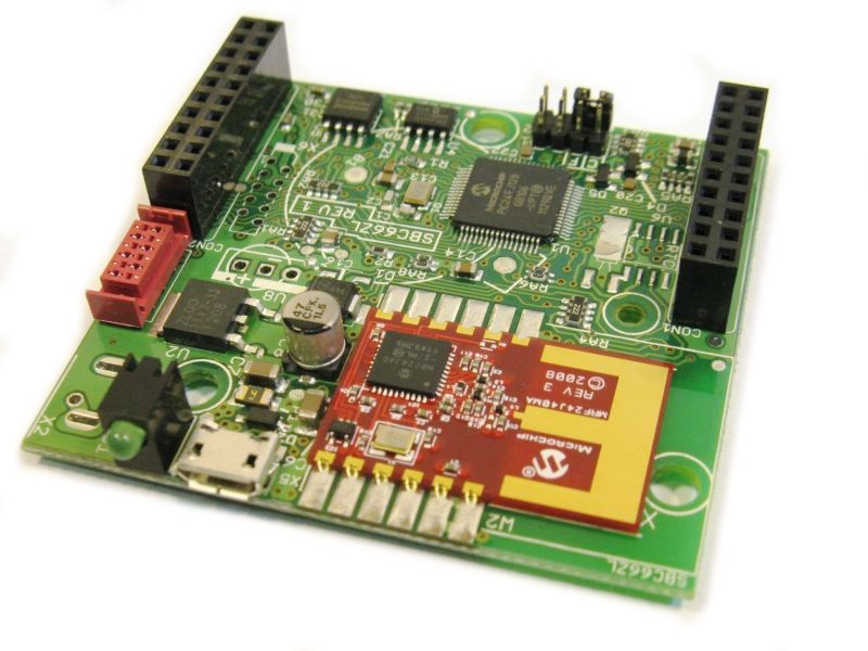
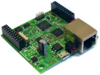
SBC66ZL Board
This product has been retired. DO NOT use for new designs. It is NO LONGER available!
The SBC66ZL is a low cost, Single Board Computer (SBC) with a USB (Micro B) port and space for a Wireless Module. It is a mixed 5V/3.3V board, and can be interfaced to both 5V and 3.3V components. It has 31 available ports that can be used for custom applications.
Of the 31 ports, 22 have software configurable functions. These 22 ports can be configured to be any one of a number of CPU Peripherals. Available peripherals are 4 UARTs (serial ports), 9 PWM modules (Analog outputs), 3 SPI ports, 4 External Interrupts, 9 Input Capture modules, 5 External Timer sources, and 3 Comparator Outputs.
It can be programmed with code created using the free Microchip MPLAB X IDE and XC16 C Compiler. We provide many free demo project that will help you get started quickly!
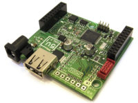
The SBC66ZL can be used as is, or as a daughter board on a larger main board. The PT66EI-24P is an example of a board that takes the SBC66ZL as a daughter board. When used as a daughter board, it can supply the main board with 5V and 3.3V power.
Please note the different power options that can be selected above! See "Power Options" section below!
Features
- Microchip PIC24FJ128GB106 Microcontroller
- USB port via standard Micro B connector.
- 128KBytes internal FLASH memory for program and constant data
- 16KBytes Bytes of internal SRAM
- 16 MIPs Microcontroller execution speed
- External 32MBit (4Mbytes) SPI FLASH
- External 8Kbyte SPI EEPROM
- 4 UARTs (RS-232, RS-485, LIN Bus...), that can be routed (via Microchip's Peripheral Pin Select feature) to any of 18 user I/O Ports
- 3 SPI Ports, that can be routed (via Microchip's Peripheral Pin Select feature) to any of 18 user I/O Ports
- 9 PWM Modules, that can be routed (via Microchip's Peripheral Pin Select feature) to any of 18 user I/O Ports
- 3 I2C ports
- 31 Digital 3.3V User I/O ports, of which 8 have on board 5V pull-up resistors to allow them to be used with 5V logic
- 11 of the I/O ports can be configured as 10-bit Analog Inputs (0 to 3.3V).
- 2.5V high precision external voltage reference for ADC converter
- Very High quality assembly, with brand name, quality components. No cheap, “no name brand” components are used!
- 3.3V Linear Regulator (Texas Instruments, ST or ON Semiconductors brand), with very high quality, brand name capacitors!
- Can be powered via Daughter Board Connector.
- Filtered analog supply to CPU for accurate analog measurements
- Daughter board connector with 20 pins for adding prototype, I/O or user expansion boards
- Micro Match connector for connecting a serial I2C device (5V or 3.3V configurable), like the LCD2S serial LCD display with keypad decoder.
- Green System LED
- Pin header with jumper that can be mounted in 3 positions: Park, "C" or "F". Software can determine what position jumper is in, and for example use "C" position to restore default configuration, and "F" position to update firmware via bootloader.
- 2.1mm power connector for standard 5.0V DC power supply, like our ..
- Very low supply current of about 25mA at 24V, or 50mA at 12V.
- Has an ICSP (In Circuit Serial Programming) connector for programming.
- Free fully functional C Compiler available from www.microchip.com
- Wide operating temperature of -40 to 85°C.
- RoHS Compliant, Lead Free
Details
It is assembled with the PIC24FJ128GB106 microcontroller, which has 128KBytes FLASH and 16KBytes SRAM. Additionally this board has 32MBit (4MByte) external FLASH and 64KBit external EEPROM.
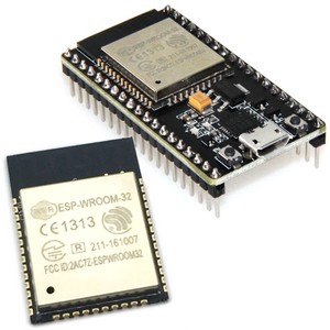
This board has space for assembling one of the following Microchip wireless modules:
- MRF89XAM8A Low Power 868 MHz Transceiver (for propriatory or MiWi communication)
- MRF89XAM9A Low Power 915 MHz Transceiver (for propriatory or MiWi communication)
- MRF24J40MA 2.4 GHz IEEE 802.15.4 Wireless Transceiver for ZigBee and MiWi
- MRF24J40MB 2.4 GHz IEEE 802.15.4 High Power Wireless Transceiver for ZigBee and MiWi
The PIC24F Microcontroller used has a feature called Peripheral Pin Select (PPS). With this feature, peripherals on the CPU can be routed to any one of the "Peripheral" I/O port pins. Available peripherals are 4 UARTs (serial ports), 9 PWM modules (Analog outputs), 3 SPI ports, 4 external interrupts, 9 input capture, 5 external timer sources, and 3 comparator outputs. For example, the 4 UARTs can be routed to the I/O pins of the daughter board connector. A possible application for this could be a board with four RS-232 or RS-485 ports (SBC66ZL used as a plug in daughter board).
The SBC66ZL is a mixed 3.3/5.0V board, making it easy to interface with both 3.3V and 5.0V devices. The 5V supply gets converted to 3.3V via an on board linear regulator. All chips on the board are 3.3V, but many of the microcontroller's I/O pins are 5.0V tolerant, allowing it to interface with 5.0V devices. Eight ports can also be configured to have 5V digital outputs. This double power supply scheme, with linear regulator for 3.3V, ensures the CPU and analog supply is clean and has low noise. For example, when connecting noisy components (like relays) to the 5V line, the CPU and analog circuitry will still run of the filtered 3.3V supply.
This board is assembled with very high quality, brand name components! Our goal is for this board to work error free for many years. For this reason, we do not use cheap components, or stress components to the limit of their capability! The quality of assembly, and reliability of components used sets this board apart from similar competitor products!
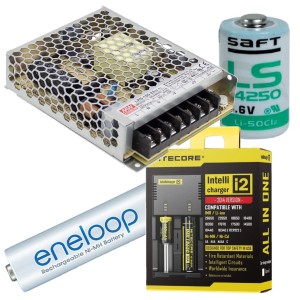
Power Options
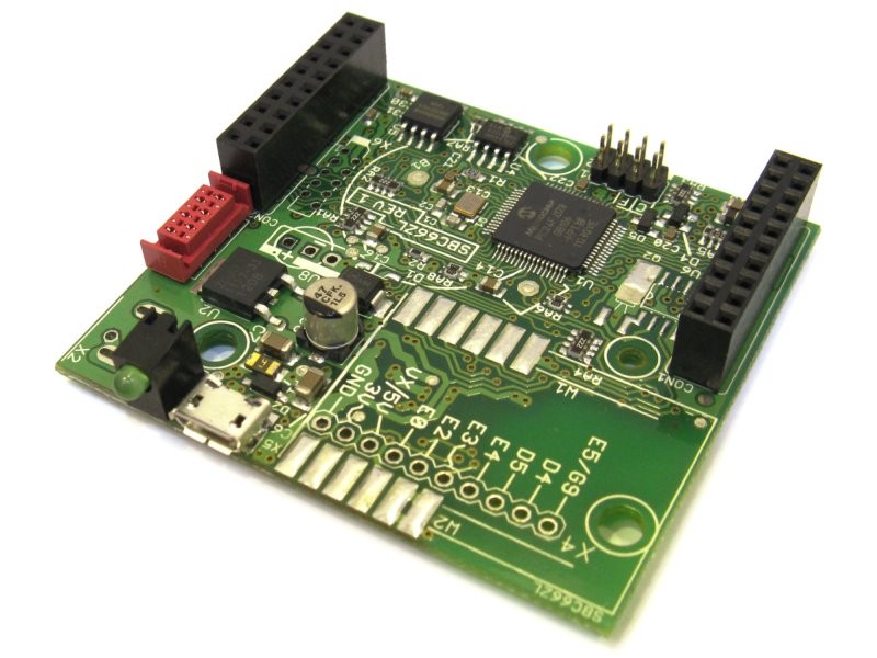
Different power options can be selected above! When "none" is selected, the SBC66ZL must be powered with a regulated 5V supply via it's USB or daughter board connector.
When one of the 18V options are selected, a 5V linear regulator (max 18V input) is mounted on the bottom of the board to convert the 18V input to 5V. If external circuitry is to be power from the SBC board's 3.3V or 5V supply, care should be taken not to exceed about 500mW of power for the 5V regulator, else it will get too hot. For example, if the board is powered via a 9V supply, this allows for about 125mA (0.5 / (9-5)) to be used by external circuitry. Up to 2A can however by used from the supply voltage (9V for this example).
The board can be powered via the power connector (2.1mm or terminal block), USB Micro B connector, or the Daughter Board Connector. The 3.3V regulator on the SBC66ZL has a current rating much higher than is required. This enables custom circuitry used with this board to get power via the daughter board connector.
Default with no power connector, 5V only! |
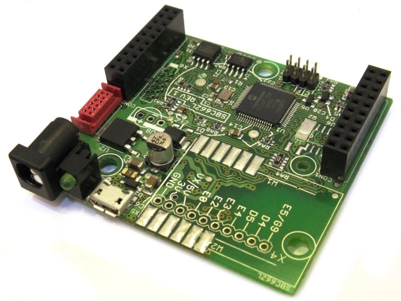
With 2.1mm power connector, 5V or 18V! |
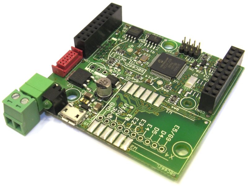
With terminal block connector, 5V or 18V! |
| Click to enlarge | ||
Expansion
The SBC66ZL board can be expanded in a many different ways to add additional functionality.
Daughter Boards

The two 2x10 Pin Female connectors (standard 2.54mm pitch) can be used to add a daughter board. Currently the following daughter boards are available.
List of Daughter Boards for SBC66: sbc66-dbs
List of board SBC66 can be used on as a Daughter Board: sbc66-as-db
- PT66ECI - Prototype board with 1 iMod port and prototyping space
- PT66EI-10P - Prototype board with 2 iMod ports, two 5 pin terminal block connectors, 3 LEDs and prototyping space
- PT66EI-24P - Prototype board with 2 iMod ports, two 12 pin terminal block connectors, 8 LEDs and prototyping space
As Daughter Board

The SBC66ZL can be mounted on a main board as a daughter board. Two 2x10 pin headers (HDR2X10-M254-575) are used on the main board to plug the SBC66ZL into. Currently the following boards can take the SBC66ZL as a daughter board.
Wireless Modules
A Microchip Wireless module can be added. Currently the following modules can be used
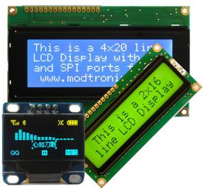
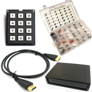
LCD Display with Keypad

One of our LCD2S serial LCD displays can be added via the I2C serial port (Micro Match connector). The LCD2S serial LCD displays also have a keyboard input, and user I/Os (relays for example). The image on the right shows the SBC66ZL connected to a 16x2 Character Serial LCD Display and a 12 Button Keypad.
Enclosure
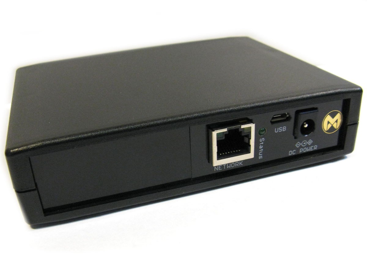
When using this board in combination with any of our PT66 prototype boards (PT66ECI, PT66EI-24P...), it can be used together with the ENC2015S-BK-NZ or ECN2015S-NZ enclosure.
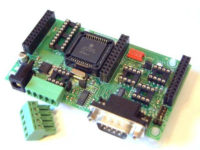
Custom

The SBC66ZL is highly configurable, and can be used in many custom applications. The picture to the right shows a custom board with 4 RS-232 Ports using a SBC66 daughter board. It uses the 4 available high speed UARTs of the SBC66ZL board. Many different applications are possible using the many UARTs (RS-232, RS-485, RS-422), PWM outputs (LED Drivers, Motor control), Analog Inputs and other available peripherals.
User Manual, Schematics and Board Revision
For the user manual, including schematics, click here.
Modifying and Upgrading the Firmware
A USB bootloader will soon be added to enable firmware upgrades by inserting a USB Flash driver into the USB port. The source code for this is already available from Microchip via their Microchip Application Library. Until then, a PIC programmer (like the PICKit 3) is required to program this board. Click here for details on programming.
To get you started quickly, we provide many example programs for this board, located in the "../src/demos" folder of the Netcruzer Download. All code is written in C, and can be edited, programmed and debugged with the free MPLAB X IDE, and compiled with the free MPLAB XC16 C Compiler. For information on modifying projects click here.
Package Includes
1 x Item as described above
| Weight | 50 g |
|---|
Based on 0 reviews
Be the first to review “SBC66ZL - SBC with USB - Retired”
You must be logged in to post a review.

There are no reviews yet.