|
Netcruzer USB Bootloader Project
V1.00
|


|
|
Netcruzer USB Bootloader Project
V1.00
|
|
This documentation is for the Netcruzer USB Bootloader. To return to the main Netcruzer documentation page Click Here.
This documentation contains information on using, configuring and building the Netcruzer USB Bootloader.
For details on programming a board with a pre-built version of the Netcruzer USB Bootloader, click here. The source code and MPLAB IDE projects is available for free, and located in the ".../src/projects/usb_hid_boot" folder of the Netcruzer Download.
The firmware is updated in a very secure manner. Even a power failure during the firmware update process will not result in the board being programmed with faulty firmware. For details, click here.
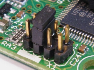
The system LED indicates the state of the board. During normal operation, the LED should have one long, and 1 to 3 short flashes per cycle, depending on the loaded firmware. For example, the Webserver firmware will have one long, and one short LED flash each 1.6 seconds. When in bootloader mode (jumper on "F"), there will always be two long flashes, followed by 1 to 3 short flashes. The state of the bootloader is:
When the board is in bootloader mode, but the USB connection is not active, the LED will have 2 long flashes, followed by 1 short flash every 3.2 seconds.
| 3.2 Seconds (times below in ms) |
| 400 On | 400 Off | 400 On | 400 Off | 100 On | 1500 Off |
LED flash pattern is 400ms ON, 400ms OFF, 400ms ON, 400ms OFF, 100ms ON, 1500ms OFF.
When the board is in bootloader mode, and the USB port is plugged in and initialized, the LED will have 2 long flashes, followed by 2 short flashes every 3.2 seconds. New firmware can be uploaded via the Netcruzer USB Bootloader application.
| 3.2 Seconds (times below in ms) |
| 400 On | 400 Off | 400 On | 400 Off | 100 On | 100 Off | 100 On | 1500 Off |
LED flash pattern is 400ms ON, 400ms OFF, 400ms ON, 400ms OFF, 100ms ON, 200ms OFF, 100ms ON, 1200ms OFF.
There will always be a minimum of two separate programs located on the Microcontrollers FLASH program memory:
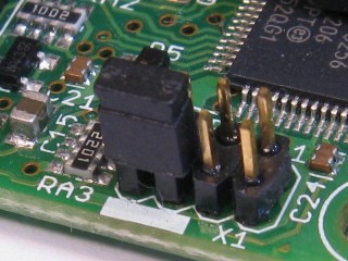
When the board is powered, the bootloader program will be executed. It will check the jumpers of the board. If the the jumper is in the "Park" position (or removed), the
| ||||||||||||||||
| FLASH Program Memory Map - Word addresses |


 1.8.4
1.8.4