No products in the cart.
iMod Modules
Description
iMod Modules are small breakout boards that provide interface or I/O functionality. They have two rows of pin headers spaced 0.7" (or 0.9" for some larger modules) apart, allowing them to be mounted on a breadboard or standard 0.1" grid prototype board. They are however designed to plug into iMod ports, that are located on many Modtronix and Netcruzer board.
They are available with different pin headers, allowing them to be plugged, soldered or pressed into the target board. See the "Pin Headers" section at the bottom of this page for details.
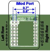
All iMod Modules have two rows of connectors, a left and a right row. The signals on these connectors are pre-defined, allowing modules to be interchangeable. On the iMod Port, pin 1 (top most pin) of the left row will have a white marking around it. Most iMod Ports will have multiple left and right rows, situated next to each other. This allows iMod Modules of different widths to be mounted. The first picture below shows a typical iMod Port with two left rows, and a single right row. This allows iMod Modules of 0.6" and 0.7" to be mounted. If an iMod Port has multiple left or right rows, the adjacent pads are connected, as shown (with blue lines) in this picture.
A single iMod Module is defined to have a maximum row spacing of 0.7”, referred to as one module width. Modules can however be wider than one module width, other common module widths are 0.9”, 1.1” and 1.6”. Target boards can provide iMod Ports for fitting iMod modules. An iMod Port is very simple and cheap to implement, only two rows of 1.00mm pads 0.7” apart are required (with a 0.1”, that is 2.54mm, grid). Modules wider than 0.7” will normally take up two iMod Ports on the target board. Adjacent iMod Ports should be spaced 0.2” apart. To help inserting the iMod module correctly into the iMod Port, pin 1 of the left connector is marked (white band around pad) on the iMod Module and iMod Port, and should always be aligned!
|
| Some text |
| Click to enlarge | ||
iMod Port Pins
| The pins of an iMod Port are assigned standard signals: | ||||||||||||||||||||||||||||||||||||||||
| ||||||||||||||||||||||||||||||||||||||||
Multiple left or right rows
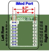
Most iMod Ports will have multiple left and right rows, situated next to each other. This allows iMod Modules of different widths to be mounted. The pictures below show some typical iMod Ports with multiple left and/or right rows. This allows iMod Modules of different widths to be mounted.
If an iMod Port has multiple left or right rows, the adjacent pads are electrically connected. This is shown with blue lines in the pictures below.
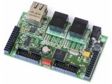
Shows iMod module with two left rows. This allows iMod Modules of 0.6" and 0.7" to be mounted. | Shows a SBC board with 3 iMod Ports. The first port is 0.9" wide, and the other two the standard 0.7". Because each port has multiple left and right rows, iMod Modules of different widths can be fitted. |
| Click to enlarge | |
Pin Headers
iMod Module can be assembled with the following pin header options:
| No Pin Headers No pin header is assembled or included with the board. |
| Loose 3, 4 and 6.0mm Pin Headers Two unsoldered(loose) Pin Headers are supplied with the board for free. The pin(mating) length is 3.0, 4.0 or 6.0mm. The number of pins depends on the iMod board. For most boards two 1x6 pin headers are supplied. |
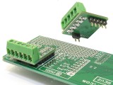
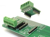
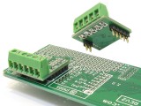
| 3.0mm Pin Headers Pin headers with 3.0mm long pins are assembled. Select this option if the module is going to be soldered into place. The picture on the right shows an example of an iMod module soldered onto a main board. Header size (2 to 8 pin) depends on iMod board. Many boards will get a 2 pin header on one side, and a 4 or 5 pin on the other. |
| 4.0mm Pin Headers Pin headers with 4.0mm long pins are assembled. Select this option if the module is going to be plugged into a low profile 5.7mm high female socket (2.54mm grid). Header size (2 to 8 pin) depends on iMod board. Many boards will get a 2 pin header on one side, and a 4 or 5 pin on the other. |
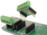
| 6.0mm Pin Headers Pin headers with 6.0mm long pins are assembled. Select this option if the module is going to be plugged into a standard 2.54mm female socket. Header size (2 to 8 pins) depends on iMod board. Many boards will get a 2 pin header on one side, and a 4 or 5 pin on the other. |
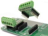
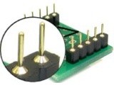
| Round Swiss Pin Headers Two 6 Pin headers with Round (Swiss) style pins are assembled. Select this option if the module is going to be plugged into female Round (Swiss) Sockets. This is very useful for prototyping! See picture on the right for some examples. Typically the 6 pin female socket (low profile version) can be used for the main board. We stock a range of swiss pin headers, available here. |
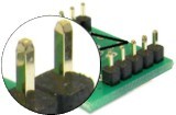
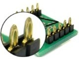
| Press-Fit Headers Press-fit type pins are assembled. They can be pressed into 1.00mm holes on a 1.6mm thick (standard PCB thickness) target board. A press-tool might be required for production assembly. Once fitted to the target board, the board is very secure, and can not be removed by hand any more. The picture on the right shows an example of an iMod module mounted onto main board via press-fit connectors. We stock a range of press-fit pin headers, available here. |
