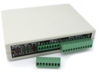
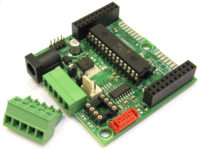
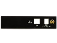
 IOR5E Input-Output-Relay Board with Enclosure and Battery Backed RTC - IOR5E
 Subtotal: US$ 43.18

Modtronix
CAN Bus module with SPI interface .
Availability:
413 in stock
SKU: CSC0-078Code: IM1CAN
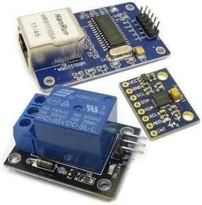
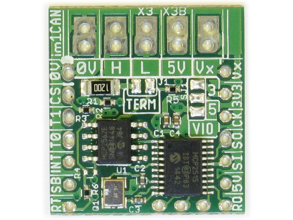
im1CAN CAN Bus Module
US$ 6.02
413 in stock
Description
Important! This board is supplied without "Pin Header" or "Terminal Block" connectors. Please contact us if either are required. See "Pin Headers" and "Order Code" sections below for details.
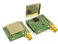
The im1CAN is a CAN Bus module(breakout board), controlled via a SPI bus. It contains both a CAN Controller and CAN Bus driver chip. It is designed to work with both 3.3V and 5V systems. The popular Microchip MCP2515 CAN Bus controller is used, allowing it to be used with many available software libraries written for this chip.
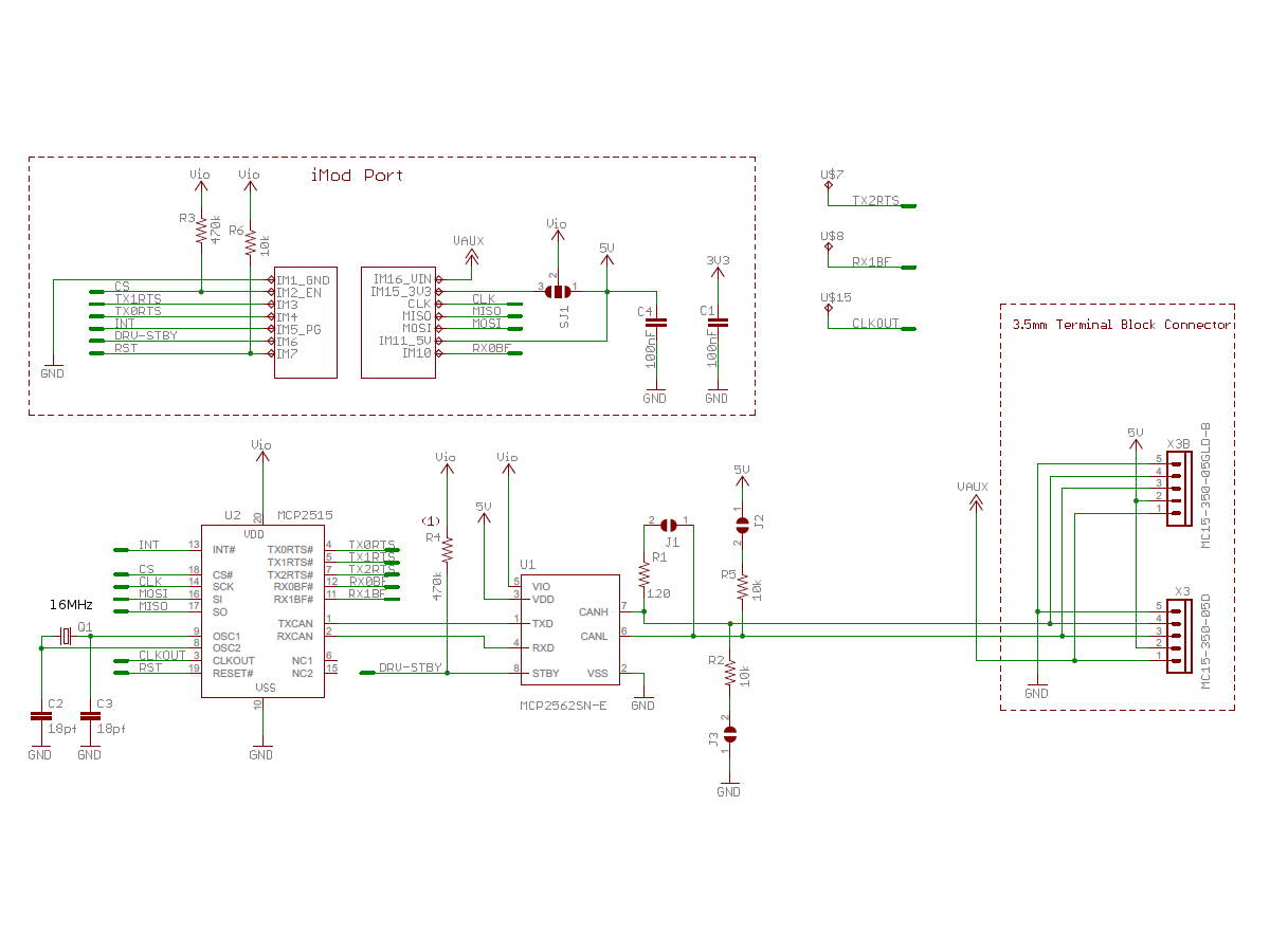
The MCP2562 CAN Bus driver is used. This chip has a separate supply and I/O voltage. The supply voltage has to be 5V, as required by the CAN Bus protocol. The I/O voltage is selected via the SJ1 solder jumper (see schematic below), and can be either 3.3V or 5V. This enables this module to be used with both 3.3V and 5V systems.
This module is designed and manufactured by Modtronix! Only high quality components from reputable suppliers are used! This is NOT a cheap module using no-name components! See "High Quality Components" section below for component details.
Top View |
Bottom View |
Dimensions |
Schematics (pdf format) |
| Click to enlarge | |||

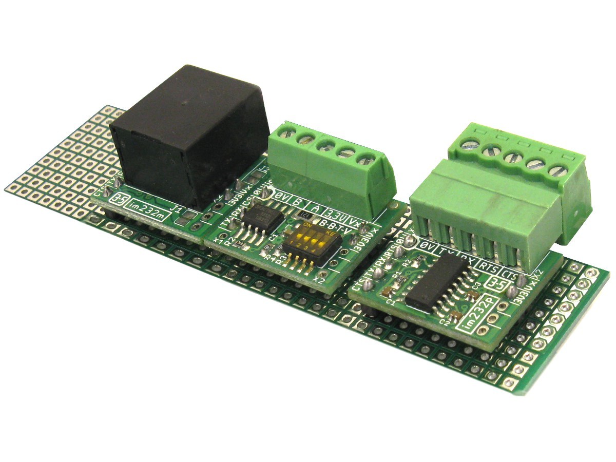
The im1Can has two rows of standard 2.54mm (0.1") pin headers. The rows are 0.7" apart, allowing this module to be mounted on a breadboard or standard 0.1" grid prototype board. The picture to the right shows some iMod modules mounted on a standard prototype board.
The pin headers supplied or soldered to this board are selected in the "Header Type" option at the top of this page.
Features
- Implements CAN V2.0B up to 1 Mb/s:
- 0 – 8 byte length in the data field
- Standard and extended data and remote frames - 2 Receive Buffers with Prioritized message storage features
- Six 29-bit filters
- Two 29-bit masks - 3 Transmit Buffers with Prioritization and Abort Features
- Clock Out Pin with Programmable Prescaler, can be used as a clock source for other device(s)
- Start-of-Frame (SOF) Signal is Available for Monitoring the SOF Signal
- Interrupt Output Pin with Selectable Enables
- Buffer Full Output Pins Configurable as:
- Interrupt output for each receive buffer
- General purpose output - Request-to-Send (RTS) Input Pins Individually Configurable as:
- Control pins to request transmission for each transmit buffer
- General purpose inputs - Interfaces Directly with Microcontrollers with 2.7V to 5.5V I/O
- 10MHz SPI Interface, supports SPI modes 0,0 and 1,1
- Implements ISO-11898-5 Standard Physical Layer Requirements
- CAN Bus Pins are Disconnected when Device is Unpowered
- An Unpowered Node or Brown-Out Event will Not Load the CAN Bus - Detection of Ground Fault:
- Permanent Dominant Detection on TXD
- Permanent Dominant Detection on Bus - Power-on Reset and Voltage Brown-Out Protection on VDD and VIO Pin
- Protection Against Damage Due to Short-Circuit Conditions (Positive or Negative Battery Voltage)
- Protection Against High-Voltage Transients in Automotive Environments
- Automatic Thermal Shutdown Protection
- Suitable for 12V and 24V Systems
- Meets or exceeds stringent automotive design requirements including “Hardware Requirements for LIN, CAN and FlexRay Interfaces in Automotive Applications”, Version 1.3, May 2012
- High ESD Protection on CANH and CANL, Meets IEC61000-4-2 greater ±8 kV
- Temperature range: -40°C to +85°C
- High quality, 3.5mm terminal block connector.
- Pin Header connectors(if selected in options above) are gold plated for best possible contact
- Module dimension: 23.7mm x 22.2mm (0.935" x 0.875")
- RoHS Compliant
Expansion
We provide many prototype boards, shields and other boards with iMod ports. Additionally we provide Eagle PCB files for these boards to all users to easily add iMod ports to their products.
Prototype boards
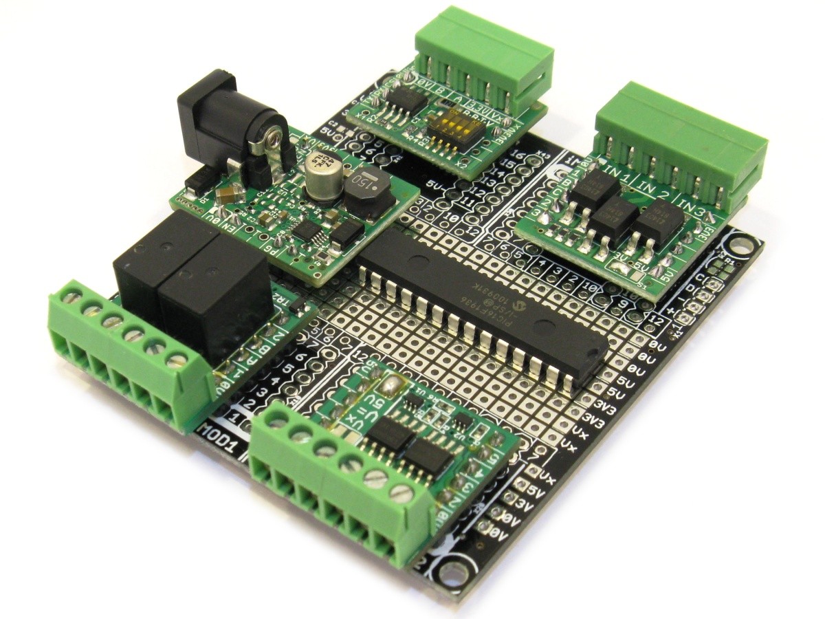
The pt2im and pt4im prototype boards have 2 and 4 iMod ports. They can be used to quickly create custom hardware using a combination of iMod modules and user specific components. Eagle PCB files are also available for free, and can easily be modified for custom applicaitons.
Pin Headers
By default this board is supplied with No Pin Headers! The following additional options can be selected in the "Header Type" Option at the top of the page (below price):
No Pin Headers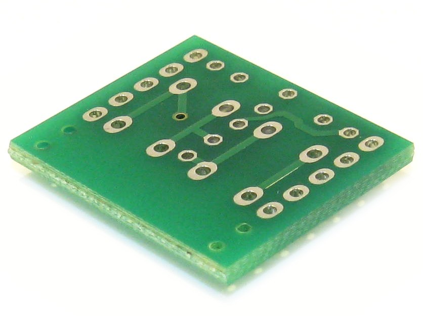 No pin header is assembled or included with the board. |
Loose 3, 4 and 6.0mm Pin Headers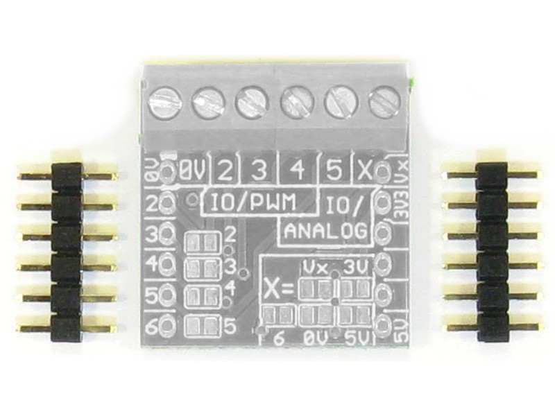 Two unsoldered(loose) Pin Headers are supplied with the board for free. The pin(mating) length is 3.0, 4.0 or 6.0mm. The number of pins depends on the iMod board. For most boards two 1x6 pin headers are supplied. |
3.0mm Pin Headers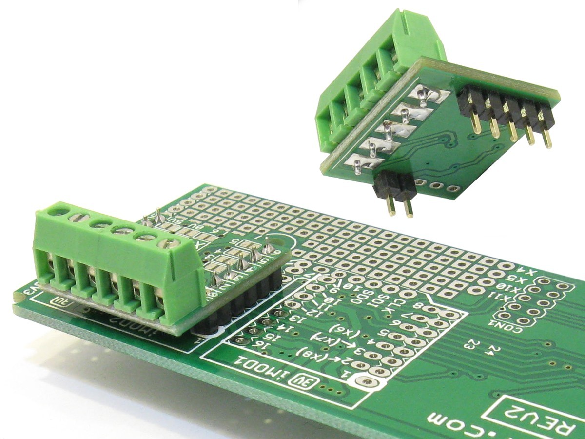 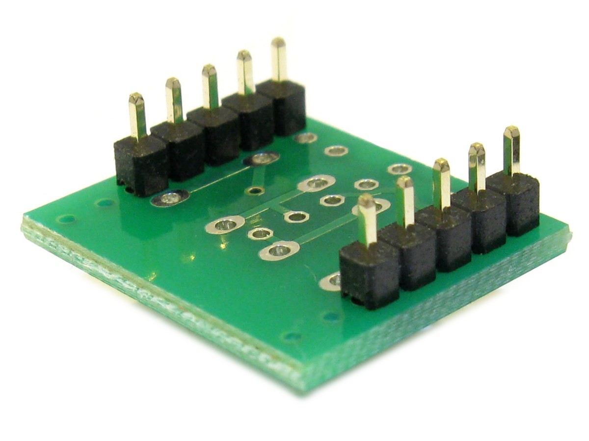 Pin headers with 3.0mm long pins are assembled. Select this option if the module is going to be soldered into place. The picture on the right shows an example of an iMod module soldered onto a main board. Header size (2 to 8 pin) depends on iMod board. Many boards will get a 2 pin header on one side, and a 4 or 5 pin on the other. |
4.0mm Pin Headers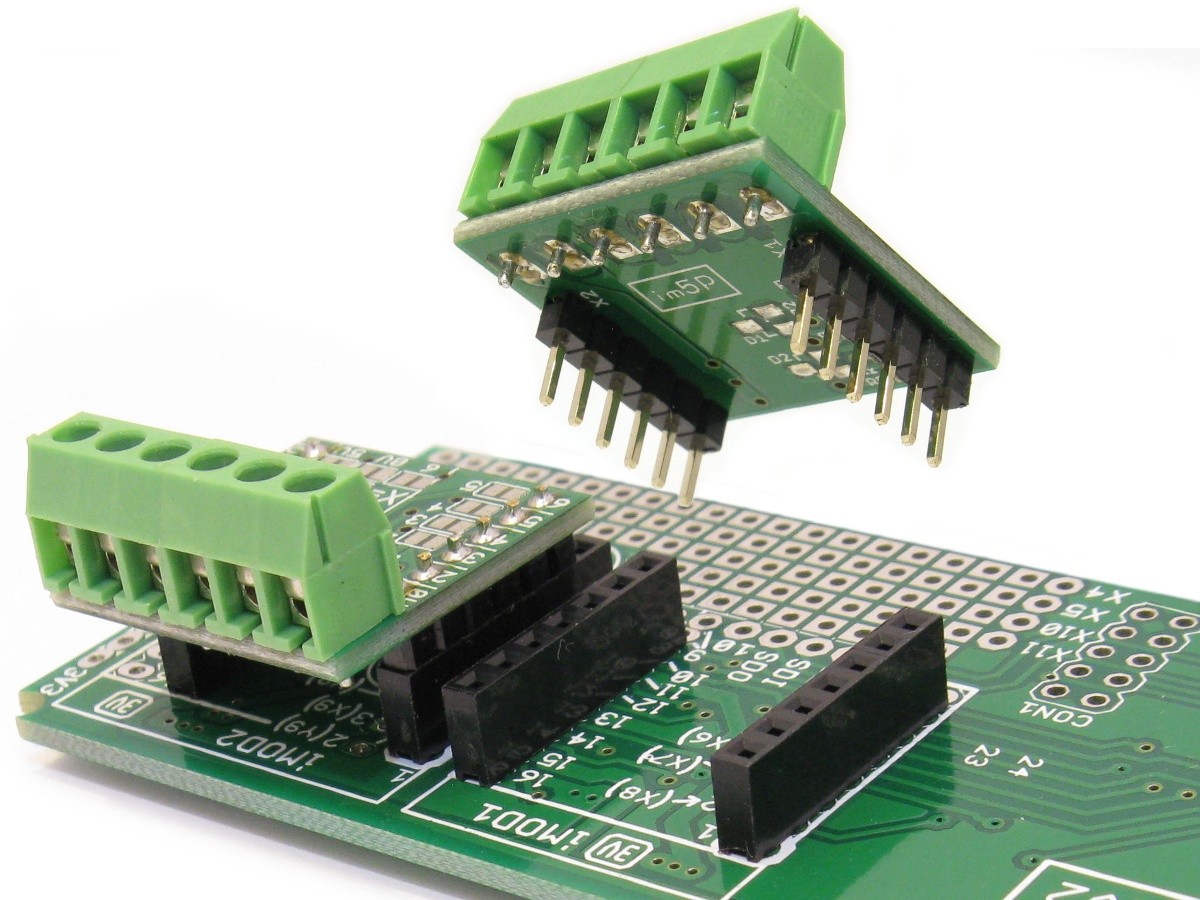  Pin headers with 4.0mm long pins are assembled. Select this option if the module is going to be plugged into a low profile 5.7mm high female socket (2.54mm grid). Header size (2 to 8 pin) depends on iMod board. Many boards will get a 2 pin header on one side, and a 4 or 5 pin on the other. |
6.0mm Pin Headers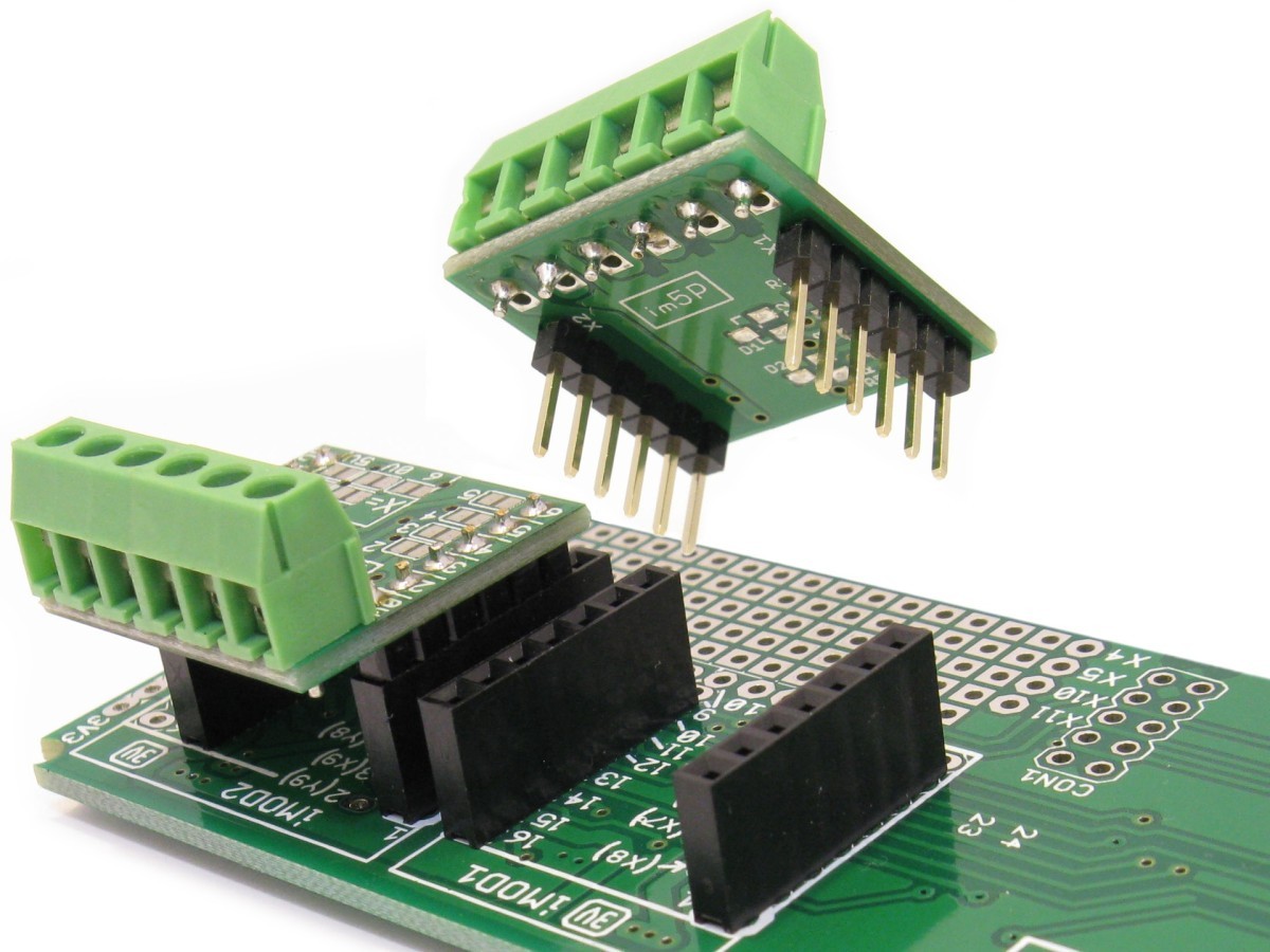 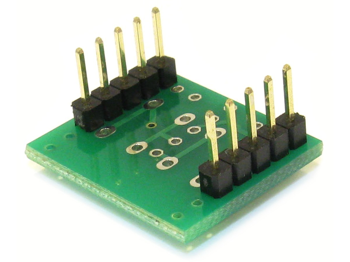 Pin headers with 6.0mm long pins are assembled. Select this option if the module is going to be plugged into a standard 2.54mm female socket. Header size (2 to 8 pins) depends on iMod board. Many boards will get a 2 pin header on one side, and a 4 or 5 pin on the other. |
Round Swiss Pin Headers  Two 6 Pin headers with Round (Swiss) style pins are assembled. Select this option if the module is going to be plugged into female Round (Swiss) Sockets. This is very useful for prototyping! See picture on the right for some examples. Typically the 6 pin female socket (low profile version) can be used for the main board. We stock a range of swiss pin headers, available here. |
Press-Fit Headers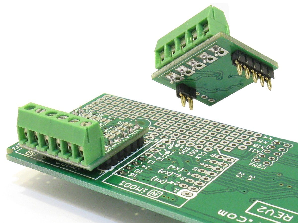  Press-fit type pins are assembled. They can be pressed into 1.00mm holes on a 1.6mm thick (standard PCB thickness) target board. A press-tool might be required for production assembly. Once fitted to the target board, the board is very secure, and can not be removed by hand any more. The picture on the right shows an example of an iMod module mounted onto main board via press-fit connectors. We stock a range of press-fit pin headers, available here. |
Code Examples
Arduino
There are many free libraries available for Arduino using the MCP2515 CAN Bus controller.
High Quality Components
This module is designed and manufactured by Modtronix! Only high quality components from reputable suppliers are used! All components have been selected to exceed the maximum rated specifications. The following components are used:
- CAN Bus controller and Driver chips: From Microchip.
- Capacitors: Capacitors are a very critical part of any electronic circuit, and often responsible for failures! We only used capacitors with much higher than required voltage rating, from reputable suppliers. Manufacturer is either AVX, Kemet, Murata, Nichicon, Panasonic, Samsung, Taiyo Yuden, TDK, Vishay or Yageo.
- Resistor: 470kOhm resistor. Manufacturer is either Rohm, Panasoic, Stackpole, Panasonic or Yageo.
- Crystal Quarts: A high quality, 20ppm crystal is used.
Documentation
| Web | Data | ||
| im1CAN Datasheet and Schematics | | ||
| MCP2515 CAN Bus Controller Datasheet | | ||
| MCP25625 CAN Bus Driver Datasheet | |
Order Code
The following order codes can be used to order this module with different terminal block options:
- im1CAN-bare - Bare, no pin header or Terminal Block assembled.
- im1CAN-tbb - With PCB mount, 3.5mm screw type terminal block (TB05B-F350-W4) assembled.
- im1CAN-tbp - With pluggable, 3.5mm terminal block header (TB05P-M350-H4) assembled, and matching terminal block plug (TB05P-F350-R4) included.
The following codes can be appended to the order codes shown above to add pin headers. See the "Pin Headers" section above for details:
- -h3l - Two loose 3.0mm Pin Headers are supplied with the board.
- -h4l - Two loose 4.0mm Pin Headers are supplied with the board.
- -h6l - Two loose 6.0mm Pin Headers are supplied with the board.
- -h3 - Two 3.0mm Pin Headers are soldered onto the board.
- -h4 - Two 4.0mm Pin Headers are soldered onto the board.
- -h6 - Two 6.0mm Pin Headers are soldered onto the board.
- -sw - Two Round Swiss Pin Headers are soldered onto the board.
- -pf - Two Press-Fit Headers are soldered onto the board.
For example, to order this board with a pluggable, 3.5mm terminal block connector, and press-fit headers assembled, use the following code:
im1CAN-tbp-pf
What is included
- 1 x iMod module, fully assembled, with pin headers and terminal block (if selected in options above).
Package Includes
1 x Item as described above
| Weight | 50 g |
|---|
Based on 0 reviews
Be the first to review “CAN Bus module with SPI interface .”
You must be logged in to post a review.
There are no reviews yet.