NRF24L01+PA+LNA with Antenna 2.4GHz Wireless Transceiver Module
Out of stock
US$ 5.58
Out of stock
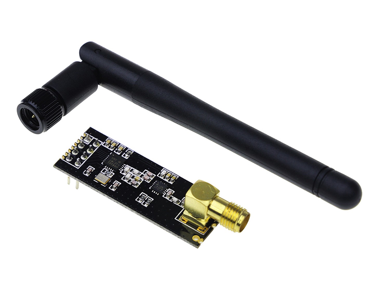
This modules contains the popular NRF24L01+ chip with PA and LNA circuit. It has a SMA connector, and is supplied with an external antenna. These improvements allow range up to 1000m(under ideal conditions).
The NRF24L01 is a highly integrated, ultra low power (ULP) 2Mbps RF transceiver for the 2.4GHz ISM (Industrial, Scientific and Medical) band. The NRF24L01+ integrates a complete 2.4GHz RF transceiver, RF synthesizer, and baseband logic including the Enhanced ShockBurst™ hardware protocol accelerator supporting a high-speed SPI interface for the application controller.
Please note: This module is assembled with a compatible Nordic NRF24L01+ tranceiver module. Nearly all NRF24L01 modules available on eBay, Aliexpress and other sites nowdays use the compatible chip, and not the original, although hardly any of them mention it!
!!! CAUTION !!!
- VCC has to be between 3.0V to 3.6V, do not exceed this range, it will destroyed the module!
- All I/O pins are 5V tolerant, and can be connected directly to port pins of a 5V microcontroller. No lever conversion is required. But, do NOT connect VCC to 5V, it will kill the board!
Features
- 250kbps to 2Mbit Data Rate
- Auto Acknowledge
- Auto Re-Transmit
- Multiceiver - 6 Data Pipes
- 32 Byte separate TX and RX FIFOs
- Software selectable channel from 2400MHz to 2525MHz (125 Selectable channels)
Specifications
- Power supply: 3.0~3.6V
- Max output power: +20 dBm
- Working current in transmit mode: 115mA
- Working current in receiver mode: 45mA
- Current in mode: 4.2uA
- Operating temperature: -20-70 degree
- Receiver sensitivity: -92dBm in 2Mbps mode, -95dBm in 1Mbps mode, -104dBm in 250kbps mode
- PA growth: 20dB
- LAN growth: 10dB
- LAN noise figure: 2.6dB
- Antenna growth: 2dBI
- 2M rate: 520m
- Transmitting rate: +7dB
- Receiving sensitivity: ≤ -90dB
- Dimensions: 15.5mm x 41mm
Additional Resources
This page from ElecFreaks has very usefull information:
www.elecfreaks.com/wiki/index.php?title=2.4G_Wireless_nRF24L01p_with_PA_and_LNA
Pins
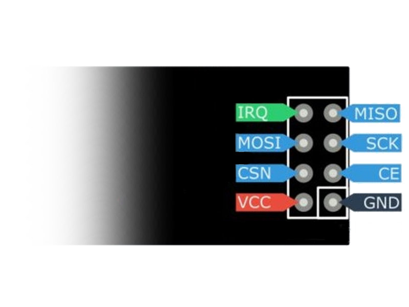
While the nRF24L01+ IC has 20 pins available, this breakout board simplifies this down to the 8 pins required to get up and running. The pins function as follows:
- VCC - This pin must NOT exceed 3.6V! Connecting it to 5V will irreversibly damage the board!
- GND - Ground
- IRQ - Interrupt pin. This pin is active LOW.
- MISO - 3.3V-5V tolerant SPI slave output.
- MOSI - 3.3V-5V tolerant SPI slave input.
- SCK - 3.3V-5V tolerant SPI clock.
- CSN - 3.3V-5V tolerant SPI chip select.
- CE - 3.3V-5V tolerant chip enable. This pin toggles the nRF24L01+ IC between transmit (TX), receive (RX), standby, and power-down mode.
Connecting to Arduino
The I/O pins can be connected directly to the port pins of a 3.3V or 5V Arduino board. But, the VCC pins can NOT exceed 3.6V! Ensure NOT to connect the VCC pin to the 5V supply of the Arduino board! Connect only to the 3.3V of your Arduino board!
Package Includes
1 x Wireless Module
1 x Antenna
| Weight | 18 g |
|---|
Based on 0 reviews
Be the first to review “NRF24L01+PA+LNA with Antenna 2.4GHz Wireless Transceiver Module”
You must be logged in to post a review.
There are no reviews yet.