ESP32-PICO-KIT ESP32 Module with USB, Male Headers

Out of stock
A$ 15.90
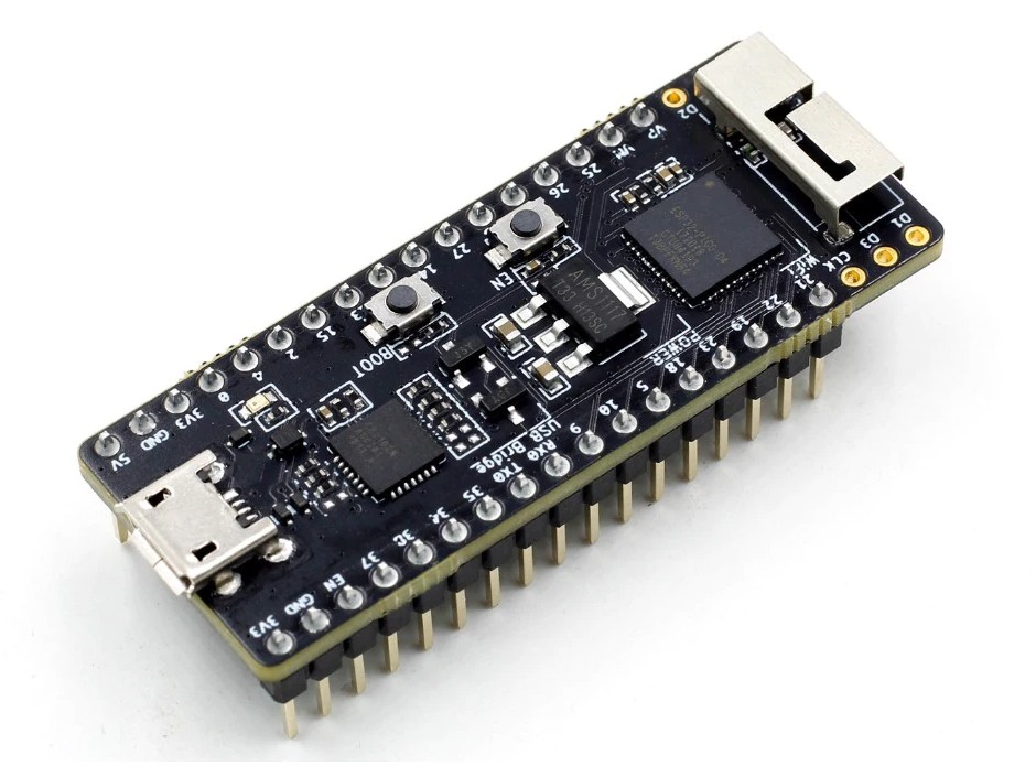
ESP32-PICO-KIT is an ESP32-based mini development board produced by Espressif.
This is a genuine, high quality module manufactured by Espressif.
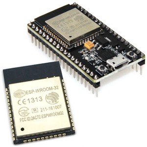
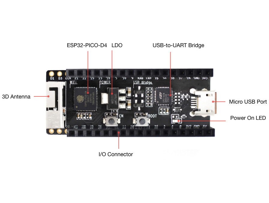
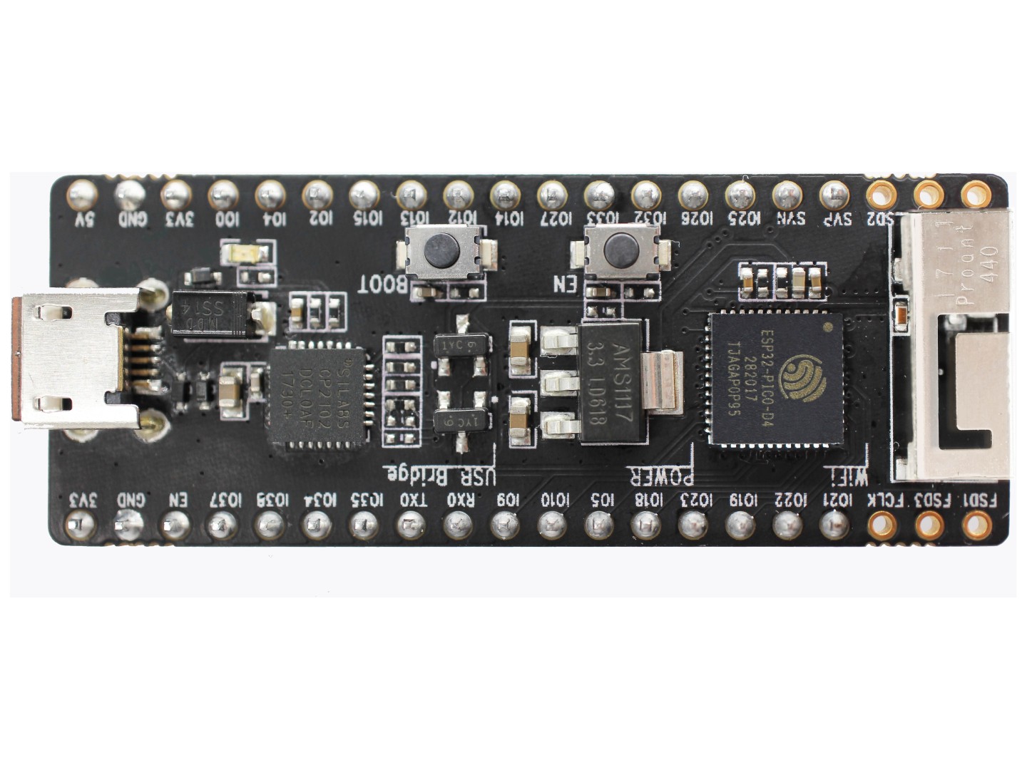
The core of this board is ESP32-PICO-D4 - a System-in-Package (SiP) module with complete Wi-Fi and Bluetooth functionalities. Compared to other ESP32 modules, ESP32-PICO-D4 integrates the following peripheral components in one single package, which otherwise would need to be installed separately:
- 40 MHz crystal oscillator
- 4 MB flash
- Filter capacitors
- RF matching links
- This setup reduces the costs of additional external components as well as the cost of assembly and testing and also increases the overall usability of the product.
The development board features a USB-UART Bridge circuit which allows developers to connect the board to a computer’s USB port for flashing and debugging.
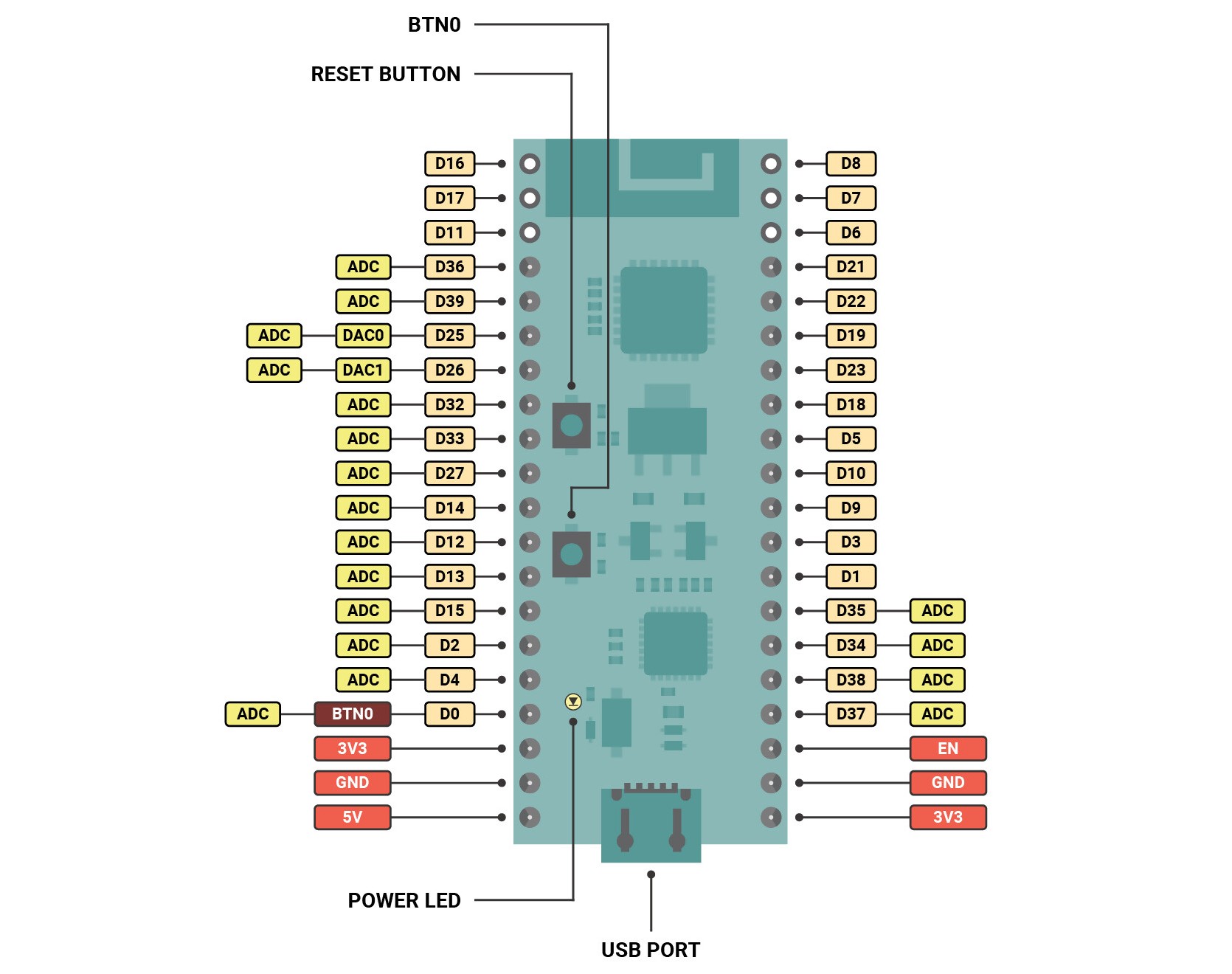
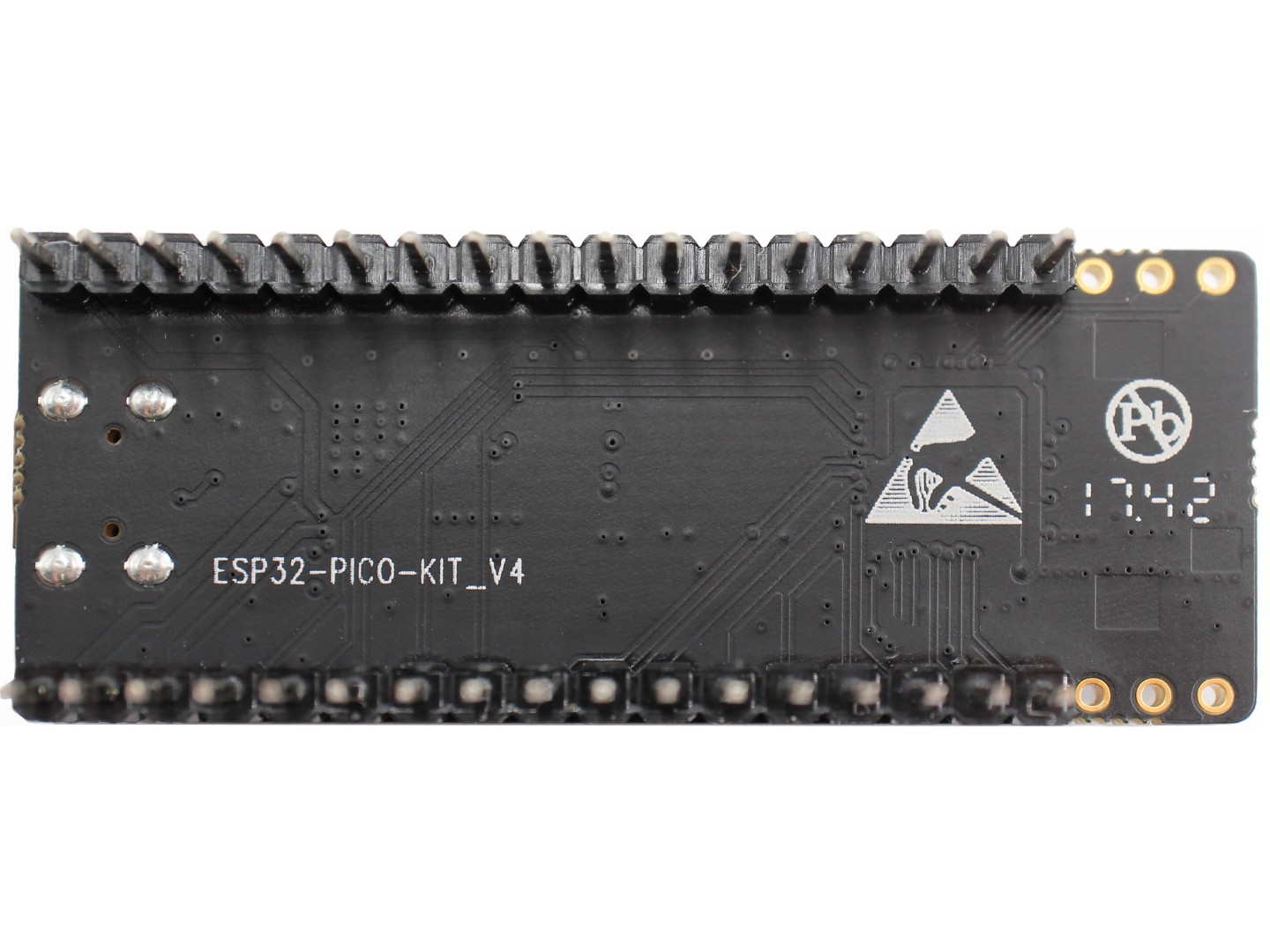
All the IO signals and system power on ESP32-PICO-D4 are led out to two rows of 20 x 0.1” header pads on both sides of the development board for easy access. For compatibility with Dupont wires, 2 x 17 header pads are populated with two rows of male pin headers. The remaining 2 x 3 header pads beside the antenna are not populated. These pads may be populated later by the user if required.
Power Supply Options
There are three mutually exclusive ways to provide power to the board:
- Micro USB port, default power supply
- 5V / GND header pins
- 3V3 / GND header pins
!!! WARNING !!!
The power supply must be provided using one and only one of the options above, otherwise the board and/or the power supply source can be damaged.
Pin Descriptions
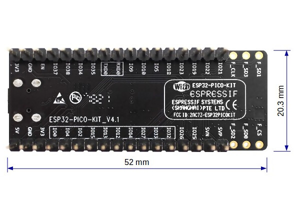
The two tables below provide the Name and Function of I/O header pins on both sides of the board, see ESP32-PICO-KIT board layout. The pin numbering and header names are the same as in the schematic given in Related Documents.
Header J2
| No. | Name | Type | Function |
|---|---|---|---|
| 1 | FLASH_SD1 (FSD1) | I/O |
GPIO8, SD_DATA1, SPID, HS1_DATA1 (See 1), U2CTS
|
| 2 | FLASH_SD3 (FSD3) | I/O |
GPIO7, SD_DATA0, SPIQ, HS1_DATA0 (See 1), U2RTS
|
| 3 | FLASH_CLK (FCLK) | I/O |
GPIO6, SD_CLK, SPICLK, HS1_CLK (See 1), U1CTS
|
| 4 | IO21 | I/O |
GPIO21, VSPIHD, EMAC_TX_EN
|
| 5 | IO22 | I/O |
GPIO22, VSPIWP, U0RTS, EMAC_TXD1
|
| 6 | IO19 | I/O |
GPIO19, VSPIQ, U0CTS, EMAC_TXD0
|
| 7 | IO23 | I/O |
GPIO23, VSPID, HS1_STROBE
|
| 8 | IO18 | I/O |
GPIO18, VSPICLK, HS1_DATA7
|
| 9 | IO5 | I/O |
GPIO5, VSPICS0, HS1_DATA6, EMAC_RX_CLK
|
| 10 | IO10 | I/O |
GPIO10, SD_DATA3, SPIWP, HS1_DATA3, U1TXD
|
| 11 | IO9 | I/O |
GPIO9, SD_DATA2, SPIHD, HS1_DATA2, U1RXD
|
| 12 | RXD0 | I/O |
GPIO3, U0RXD (See 3), CLK_OUT2
|
| 13 | TXD0 | I/O |
GPIO1, U0TXD (See 3), CLK_OUT3, EMAC_RXD2
|
| 14 | IO35 | I |
ADC1_CH7, RTC_GPIO5
|
| 15 | IO34 | I |
ADC1_CH6, RTC_GPIO4
|
| 16 | IO38 | I |
GPIO38, ADC1_CH2, RTC_GPIO2
|
| 17 | IO37 | I |
GPIO37, ADC1_CH1, RTC_GPIO1
|
| 18 | EN | I |
CHIP_PU
|
| 19 | GND | P |
Ground
|
| 20 | VDD33 (3V3) | P |
3.3V power supply
|
Header J3
| No. | Name | Type | Function |
|---|---|---|---|
| 1 | FLASH_CS (FCS) | I/O |
GPIO16, HS1_DATA4 (See 1), U2RXD, EMAC_CLK_OUT
|
| 2 | FLASH_SD0 (FSD0) | I/O |
GPIO17, HS1_DATA5 (See 1), U2TXD, EMAC_CLK_OUT_180
|
| 3 | FLASH_SD2 (FSD2) | I/O |
GPIO11, SD_CMD, SPICS0, HS1_CMD (See 1), U1RTS
|
| 4 | SENSOR_VP (FSVP) | I |
GPIO36, ADC1_CH0, RTC_GPIO0
|
| 5 | SENSOR_VN (FSVN) | I |
GPIO39, ADC1_CH3, RTC_GPIO3
|
| 6 | IO25 | I/O |
GPIO25, DAC_1, ADC2_CH8, RTC_GPIO6, EMAC_RXD0
|
| 7 | IO26 | I/O |
GPIO26, DAC_2, ADC2_CH9, RTC_GPIO7, EMAC_RXD1
|
| 8 | IO32 | I/O |
32K_XP (See 2a), ADC1_CH4, TOUCH9, RTC_GPIO9
|
| 9 | IO33 | I/O |
32K_XN (See 2b), ADC1_CH5, TOUCH8, RTC_GPIO8
|
| 10 | IO27 | I/O |
GPIO27, ADC2_CH7, TOUCH7, RTC_GPIO17
EMAC_RX_DV
|
| 11 | IO14 | I/O |
ADC2_CH6, TOUCH6, RTC_GPIO16, MTMS, HSPICLK,
HS2_CLK, SD_CLK, EMAC_TXD2
|
| 12 | IO12 | I/O |
ADC2_CH5, TOUCH5, RTC_GPIO15, MTDI (See 4), HSPIQ,
HS2_DATA2, SD_DATA2, EMAC_TXD3
|
| 13 | IO13 | I/O |
ADC2_CH4, TOUCH4, RTC_GPIO14, MTCK, HSPID,
HS2_DATA3, SD_DATA3, EMAC_RX_ER
|
| 14 | IO15 | I/O |
ADC2_CH3, TOUCH3, RTC_GPIO13, MTDO, HSPICS0
HS2_CMD, SD_CMD, EMAC_RXD3
|
| 15 | IO2 | I/O |
ADC2_CH2, TOUCH2, RTC_GPIO12, HSPIWP,
HS2_DATA0, SD_DATA0
|
| 16 | IO4 | I/O |
ADC2_CH0, TOUCH0, RTC_GPIO10, HSPIHD,
HS2_DATA1, SD_DATA1, EMAC_TX_ER
|
| 17 | IO0 | I/O |
ADC2_CH1, TOUCH1, RTC_GPIO11, CLK_OUT1
EMAC_TX_CLK
|
| 18 | VDD33 (3V3) | P |
3.3V power supply
|
| 19 | GND | P |
Ground
|
| 20 | EXT_5V (5V) | P |
5V power supply
|
The following notes give more information about the items in the tables above.
- This pin is connected to the flash pin of ESP32-PICO-D4.
- 32.768 kHz crystal oscillator: a) input b) output
- This pin is connected to the pin of the USB bridge chip on the board.
- The operating voltage of ESP32-PICO-KIT’s embedded SPI flash is 3.3V. Therefore, the strapping pin MTDI should hold bit zero during the module power-on reset. If connected, please make sure that this pin is not held up on reset.
Documentation
For additional information, see the manufacturer's product page.product page:
docs.espressif.com/projects/esp-idf/en/latest/hw-reference/get-started-pico-kit.html
For the Circuit Schematic in PDF format, click here.see this page:
99tech.com.au/m/esp32-pico-kit_schematic_v4.1.pdf
Package Includes
1 x ESP32-PICO-KIT module
| Weight | 10 g |
|---|---|
| Quantity | 1 |
| Voltage | 3.3V |
| Brand |