SBC28PC-IR4
171 in stock
US$ 24.41
171 in stock
Description
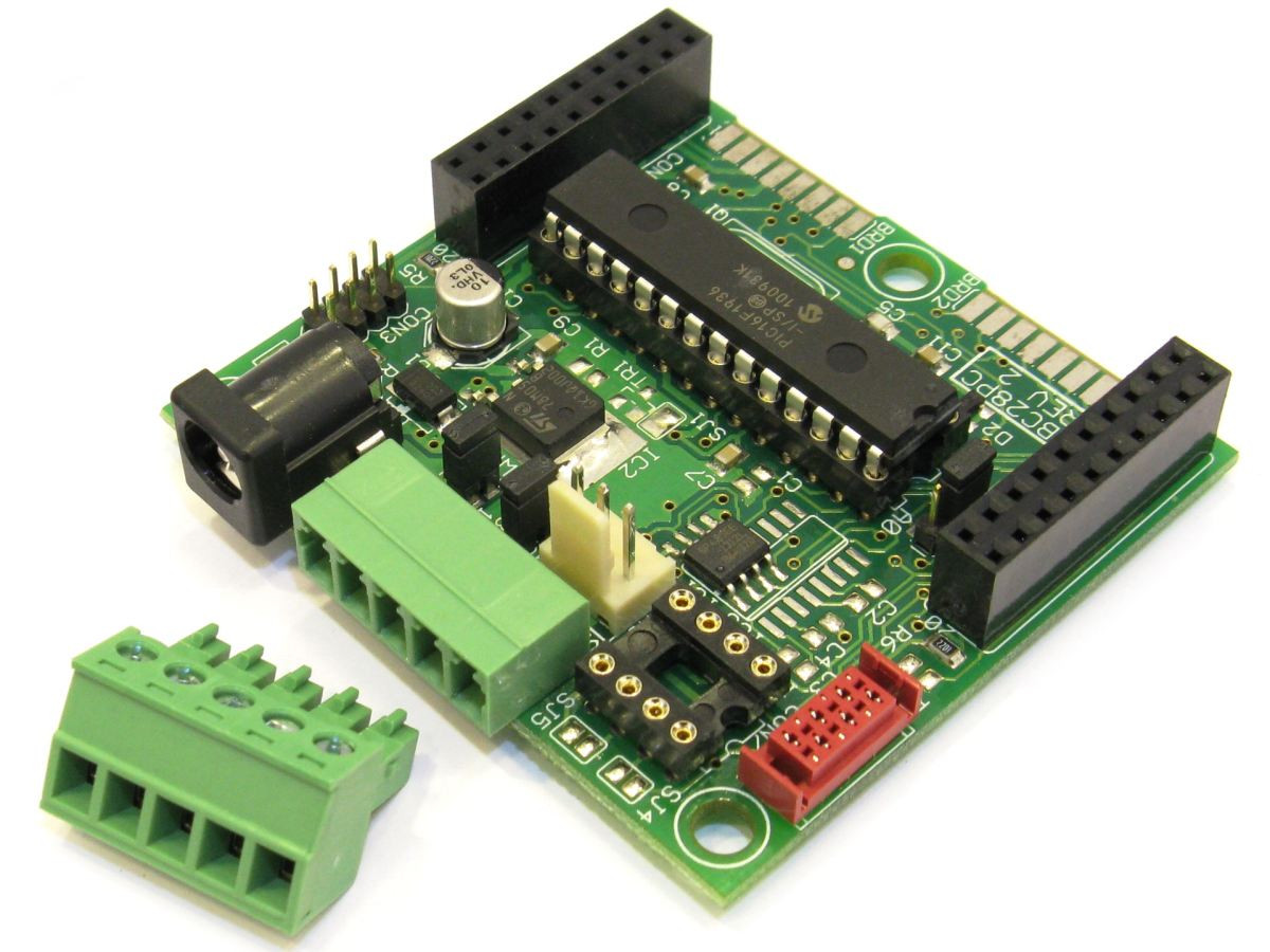
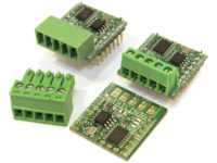
Compact SBC for 28 pin PIC with RS485 and CAN BUS interface - fully assembled (CPU not included).
The SBC28PC is a single board computer for 28 pin PIC microcontrollers. It has a RS485 serial port, and socket for a MCP2551 CAN Bus driver chip (for PIC chips that have a CAN Bus). Please not, the CAN Bus driver chip (MCP2551) is NOT included by default! The RS485 is available via a 3 pin molex connector, and a 5 pin 3.81mm terminal block connector(configured via solder jumpers). When the CAN BUS driver chip is inserted, the CAN signals are available on the 5 pin terminal block connector (RS485 is only on 3 pin molex connector in this case). Some examples of 28 pin DIP PIC chips that this board is designed for (There are many more!):
- PIC18F23K22, PIC18F24K22, PIC18F25K22, PIC18F26K22
- PIC18F242, PIC18F252, PIC18F248, PIC18F258
- PIC18F2320, PIC18F2410, PIC18F2680 (CAN BUS), PIC18F2550 (USB)
- PIC16F870, PIC16F873(A), PIC16F876(A)
- PIC16C63, PIC16C66, PIC16C73(A), PIC16F73, PIC16C76, PIC16F76
- PIC16F872, PIC16C62(A), PIC16C72 (These chips do not have a UART, requires software UART)
Most other 5V, 28 pin PIC chips will also work, as long as their power, reset(MCLR) and oscillator pins are situated in the same place as the chips listed above.
The following new PIC chips with CAN Bus can also be used. A small hardware modification is required. A 10uF 16V capacitor must be soldered between pin 6 and 8 of the PIC on the bottom of the board. We can do this free of charge on request. A very small ceramic capacitor is used, that is barely noticeable. Daughter board pin A4 is not available for this mode(Vcap pin with capacitor connected to it). We recommend using a 16MHz crystal for this version, seeing that this will allow full 64MHz operation of PIC chip.
- PIC18F25K80, PIC18F26K80
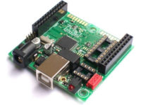
When using this board with the CAN driver chip, it must be used with a PIC chip that has an onboard CAN peripheral, like the PIC18F248, PIC18F258, PIC18F2680.... chips. This board can also be used with the PIC18F2550 PIC with built in USB. In this case, a USB socket has to be added (on a prototype Daughter or Frontend board for example).
By default these boards don't have a crystal assembled. A Crystal is not required seeing that all PIC chips have built in crystals. Typically the built in crystal is 4MHz or 8MHz. If a higher or special clock rates is required, it can be selected via the options below. For example, if this board is going to be used to communicate at a standard BAUD rate (9600, 19200, 38400, 57600, 115200...), then the 18.432MHz crystal should be selected below. With this crystal, the exact BAUD rate can be obtained with 0% error.
Features
- 22 I/O ports when using common PIC chips, for example the PIC16F876A or PIC18F252.
- Is part of our MicroX product range, and has a Frontend and Compact Daughter board connector for expansion. For details see www.modtronix.com/microx.
- Compact size of 58mm x 54mm. For details see www.modtronix.com/microx/dimensions.
- Assembled with High Quality, Industrial Temperature components - electrolytic capacitors used are extra long lifetime rated!
- Diode protected 2.1mm power connector for a standard DC transformer.
- Wide operating voltage range from 7 – 30V.
- On board 15kV ESD protected RS485 interface. Assembled with industrial temperature range interface driver chip.
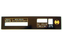
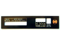
- 5 pin 3.81mm terminal block connector with RS485 or CAN BUS signals (when CAN interface driver is assembled), ground and external power.
- The power pin on the 5 pin terminal block connector can be connected to the boards unregulated power supply (the input of the 2.1mm power connector) via a strap. This can be used to:
- Provide power for all other boards daisy chained to this one. For this to work this board must be powered via its 2.1mm power connector! It will supply power to all other boards daisy chained to it.
- Obtain power for this board. In this case no power has to be supplied via the 2.1mm power connector. It will obtain it's power via the 5 pin terminal block connector.
- Power LED to indicate when device is powered.
- Micro Match socket with Power, I2C and SPI signals. The Micro Match connector can be used to daisy chain multiple I2C devices together, like our LCD2S Serial LCD displays with keyboard decoder. For details, click here.
- Has an ICSP (In Circuit Serial Programming) connector (ICPC1 type) - CPU can be programmed in circuit. For details see Programming Modtronix PIC based boards.
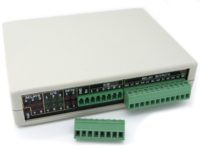
Expansion
This board has a daughter board connector, allowing following board to be plugged into it:
- IOR5E prototype main board, with enclosure
- PT01TC and PT01TC-KITprototype daughter boards
- PT10E prototype main board, with enclosure
- PT24E prototype main board, with enclosure
Programming
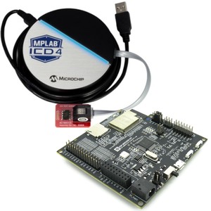
This board has a small, 8 pin connector(2.0mm pitch) containing the ICSP(in circuit serial programming) pins. To program the board, a PIC programmer(like the ICD5 or PICKit 5) and the PGM06(with ICD) or PGM2KIT(with PICKit) adapter is required. For details, see this page.
Documentation, Details, Schematics, Example Code...
Package Includes
1 x SBC Board
1 x 5 Pin 3.81mm Terminal Block Plug (TB05P-F381-R4)
| Weight | 40 g |
|---|
Based on 0 reviews
Be the first to review “SBC28PC-IR4”
You must be logged in to post a review.
There are no reviews yet.