SBC66EC - SBC with Ethernet and USB
215 in stock
US$ 49.88
215 in stock
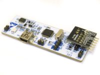
SBC66EC Board
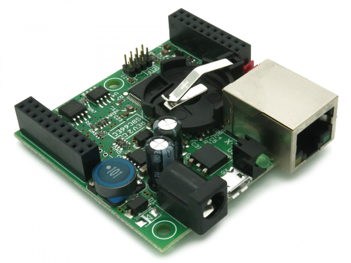
The SBC66EC is a Single Board Computer (SBC) with a 10/100 Mbit/sec Ethernet and a micro USB port. It is supplied programmed with a USB Bootloader(for upgrading Firmware) and Webserver(firmware) installed. The Webserver firmware uses the TCP/IP and USB stack from the Microchip Application Library. It has a web interface for monitoring, controlling and configuring the board. This functionality will be extended in future releases. The USB port is mostly used for debugging, sending commands and requesting information. The TCP/IP stack supports the following protocols:
- ARP, IP, ICMP, UDP, TCP, DHCP, SNMP, HTTP, FTP, TFTP
- Socket support for TCP and UDP
- Secure Sockets Layer (SSL)
- NetBIOS Name Service
- DNS Domain Name System
- Ethernet Device Discovery
It implements DHCP and NetBIOS, which makes it very easy to access on a network - no configuration of static IP addresses are required! When connected to a network with a DHCP server, it will automatically be assigned an IP address. If no DHCP server is present, the board will be assigned it's default IP address. The default IP address and NetBIOS name is 10.1.0.1 and "mchpboard", and can be changed via the web interface. To access the board on a network with DHCP enabled, the NetBIOS name or assigned IP address (have to get that from DHCP server) can be used. For example, with the default NetBIOS name, the board's web interface can be viewed in a browser by using the following address: http://mchpboard On a network without DHCP, the default IP address can be used: http://10.1.0.1
The web pages are stored in an on-board 4MByte FLASH. All source code for the default web pages, and example web pages are provided. Custom pages can easily be created by modifying the default or example web pages. Web pages can be uploaded in many different ways, including the web interface(using a standard browser), command line script file, or the Microchip MPFS2 Utility. Click here for details.
The SBC66EC can be used as is, or as a daughter board on a custom designed main board. The PT66EI-24P is an example of a board that takes the SBC66EC as a daughter board. When used as a daughter board, it can also supply the main board with a couple of 100mA of 3.3V and 5V power.
Details
It is assembled with the PIC24FJ256GB206 microcontroller, which has 256KBytes FLASH and 96KBytes SRAM. Additionally this board has 32MBit (4MByte) external FLASH and 64KBit external EEPROM. The Microchip TCP/IP (with Web Server, DHCP, Email, SNMP, Dynamic DNS...) and USB stack (CDC mode) only use 28% of the FLASH and 7% of the RAM.
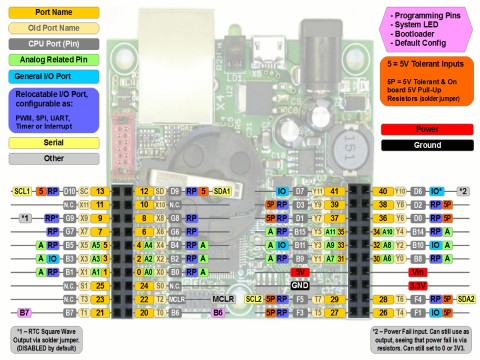
The PIC24F Microcontroller used has a very nice feature called Peripheral Pin Select (PPS). This is a great feature, and very well suited for a general purpose SBC board like this. With this feature, peripherals on the CPU can be routed to any one of the "Peripheral" I/O port pins. For example, the PIC has 4 USART's, which can now all be routed to the I/O pins of the daughter board connector if required. This would make it possible designing a main board with 4 RS-232 or RS-485 ports by using the SBC66EC as a plug in daughter board. Other peripherals available via the PPS feature are 9 PWM modules (Analog outputs), 3 SPI ports, 4 external interrupts, 9 input capture, 5 external timer sources, and 3 comparator outputs.
It also has a RTC (real time clock) with battery holder for a CR2032 battery, which can provide more than 20 years of backup time (assuming board is connected to external power most of the time).
There are plenty of Digital Inputs, Digital Outputs, Analog Inputs, PWMs and more available via two daughter board connectors and a 10 pin FFC connectors.
The SBC66EC accepts a wide supply voltage from 7.5V to 40V. It has a dual 3.3V and 5.0V power supply, making it easy to interface with both 3.3V and 5.0V devices. All chips on the board are 3.3V, but most of the microcontroller's I/O pins are 5.0V tolerant, allowing it to interface with 5.0V devices. Eight ports can also be configured to have 5V digital outputs. The 5V power supply is a high quality 500mA DC/DC Converter from National Semiconductors, with shielded Inductor and very high quality, long life capacitors. A linear regulator is used for the 3.3V supply. This double power supply scheme, with linear regulator for 3.3V, ensures the CPU and analog supply is clean and has low noise.
The board can be powered via a 2.1mm power connector, the Ethernet port (PoE), the USB port (solder jumper), or the daughter board connector. Passive PoE can be used to power the board via the spare Ethernet pairs (possitive on 4&5, ground on 7&8) with a voltage between 7V to 40V. There are many commercial Passive PoE injectors and switches available that do just this. We recommend using a 24V Passive PoE switch, seeing that no injector (and additional cables) is required. The 5V and 3.3V regulators on the SBC66EC have current ratings much higher than is required. This enables custom circuitry used with this board to get power via the daughter board connector. For details, download the user manual.
This board is assembled with very high quality, brand name components! Our goal is for this board to work error free for many years. For this reason, we do not use cheap components, or stress components to the limit of their capability! The quality of assembly, and reliability of components used sets this board apart from similar competitor products!
Features
- Assembled with the Microchip PIC24FJ256GB206 Microcontroller
- 10/100 MBit/sec Ethernet port
- USB port via Micro B USB connector. Can also power board
- 256KBytes internal FLASH memory for program and constant data
- 96KBytes Bytes of internal SRAM
- 16 MIP Microcontroller execution speed
- External 32MBit (4Mbytes) SPI FLASH
- External 8Kbyte SPI EEPROM
- External RTC with CR2032 Battery holder, can provide backup power for over 20 years (assuming SBC board is powered most of the time)
- 4 USARTS (RS-232, RS-485, LIN Bus...), that can be routed (via Microchip's Peripheral Pin Select feature) to any of 18 user I/O Ports
- 2 SPI Ports, that can be routed (via Microchip's Peripheral Pin Select feature) to any of 18 user I/O Ports
- 9 PWM Modules, that can be routed (via Microchip's Peripheral Pin Select feature) to any of 18 user I/O Ports
- 2 I2C ports
- 26 Digital 3.3V User I/O ports, of which 8 have on board 5V pull-up resistors to allow them to be used with 5V logic
- 11 of the I/O ports can be configured as 10-bit Analog Inputs (0 to 3.3V).
- 2.5V high precision external voltage reference for ADC converter
- Very High quality assembly, with brand name, quality components. No cheap, “no name brand” components are used!
- 5V Switch Mode Regulator (National Semiconductors), with very high quality, brand name capacitors!
- 3.3V Linear Regulator (Texas Instruments, ST or ON Semiconductors brand), with very high quality, brand name capacitors!
- Can be powered via Passive PoE. Like a 24V Passive PoE switch, or a Passive PoE injector for example.
- Filtered analog supply to CPU for accurate analog measurements
- Daughter board connector with 20 pins for adding prototype, I/O or user expansion boards
- 10 pin FFC (Flat Flexible Cable) connectors with power and 8 I/O port. Uses standard 10 pin, 1.0mm spacing FFC cable
- Micro Match connector for connecting a serial I2C device (5V or 3.3V configurable), like the LCD2S serial LCD display with keypad decoder.
- Red System LED
- Shielded RJ45 network connector with link and activity LEDs
- Pin header with jumper that can be mounted in 3 positions: Park, "C" or "F". Software can determine what position jumper is in, and for example use "C" position to restore default configuration, and "F" position to update firmware via bootloader.
- 2.1mm power connector for standard DC transformer.
- Very low supply current of about 25mA at 24V, or 50mA at 12V.
- Has an ICSP (In Circuit Serial Programming) connector (ICPC1 type) - CPU can be programmed in circuit. For details see Programming Netcruzer boards
- Free fully functional MPLAB XC16 C Compiler available from www.microchip.com
- Wide operating voltage range from 7.5V to 40V.
- Wide operating temperature of -40 to 85°C.
- RoHS Compliant, Lead Free
User Manual, Schematics and Board Revision
- For the user manual, including schematics, click here.
- Microchip TCP/IP stack documentation in pdf format and in Windows Help File format (*.chm).
Modifying and Upgrading the Firmware
The latest, pre-built firmware is available here, and can be upgraded via the Netcruzer USB Bootloader or the Web interface.
Alternatively the source code can be downloaded, modified, and used to update the board. The SBC66EC is supplied programmed with two completely independant programs, the USB Bootloader(for upgrading Firmware) and Webserver(actual firmware). The USB Bootloader is used to upgrade the Firmware via USB, and would normally not be modified. The Webserver is the default firmware at delivery, and can be replaced with any other program. Full source code for the USB Bootloader and Webserver is located in the "../src/common_proj" folder of the Netcruzer Download. All code is written in C, and can be edited, programmed and debugged with the MPLAB X IDE, and compiled with the MPLAB XC16 C Compiler. For information on modifying projects click here.
The USB Bootloader allows the firmware to be upgraded via the Netcruzer USB Bootloader application. Additionally firmware and webpages can also be updated via the Web Interface.
The Webserver ships with Default Web Pages, written in standard HTML and JavaScript. Full source code is available in the ".../src/common_proj/webserver/WebPages/Default" folder of the Netcruzer Download. Web pages can be edited with any text editor, and uploaded to board as described here. The Webserver uses the TCP/IP and USB stack from the Microchip Application Library, which has a very rich feature set (Web Server, DHCP, Email, SNMP, Dynamic DNS...).
', 'SBC66EC - SBC with Ethernet and USB', '
Single Board Computer with Ethernet and USB ports.
Package Includes
1 x Item as described above
| Weight | 51 g |
|---|
Based on 0 reviews
Be the first to review “SBC66EC - SBC with Ethernet and USB”
You must be logged in to post a review.

There are no reviews yet.